

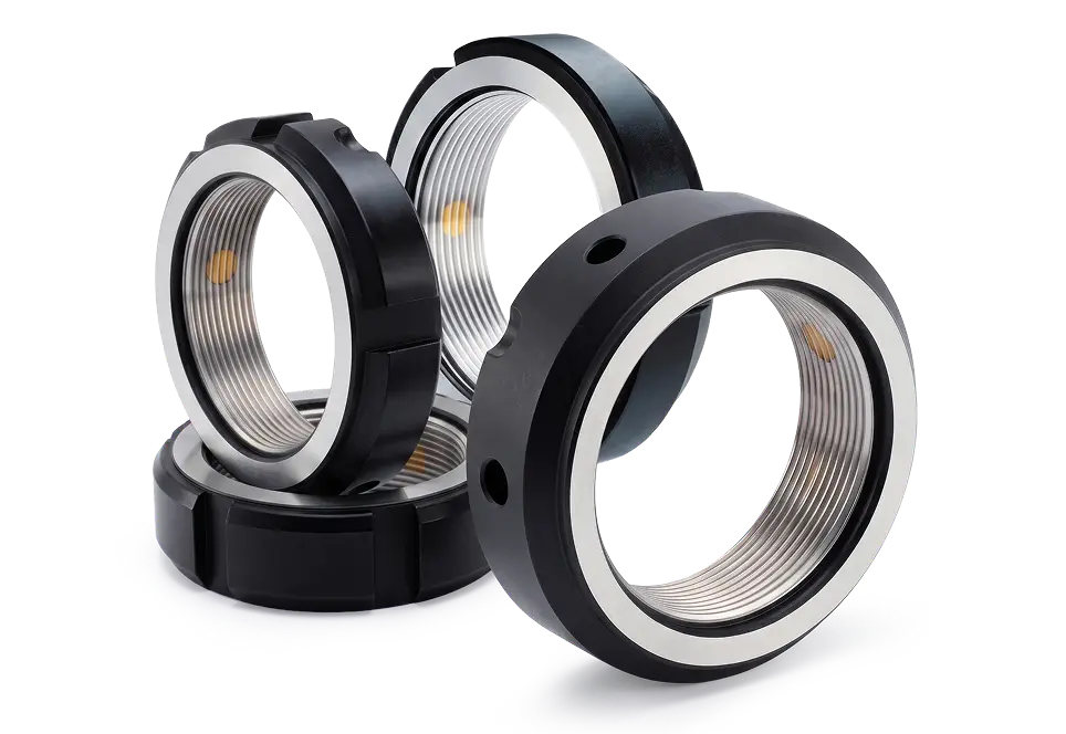

How 30° Flank Locking Works
The set screws in a 30° flank locknut never bear on the shaft directly. Each screw drives a brass pad that seats against the thread flank at a 30° radial angle, spreading the clamping load along the flank rather than denting the thread crest. That geometry is what lets the nut lock on a plain threaded shaft, and it's why the same nut comes off and goes back on without damage.
Conventional locking methods work around the problem instead of solving it. A tab washer needs a slot cut in the shaft. A grub screw bearing straight onto the thread deforms it, and the nut is then a single-use part. Flank locking through a soft pad avoids both.


No thrust washer or keyway
The locking happens between the set screws, the brass pads, and the thread flank, all inside the nut. Nothing else goes on the shaft, the shaft keeps its full section strength, and a machining operation comes off the drawing.

Reusable
The brass pad rather than the shaft thread is what deforms, so assemblies can be broken down and rebuilt. That matters on gearboxes and pump housings that get opened for maintenance rather than scrapped.

Two grades, one geometry
The same envelope is available ground or precision turned. You pay for 0.002 mm run-out where the application justifies it and 0.005 mm where it doesn't, without redesigning the housing around a different nut.

Face and thread finished together
On the grinding grades the contact face and thread are finished in one process, so the face the bearing sits against runs true to the thread that positions it.
Choosing Between MF, MFZ, BF, BFZ, TMF and SFZ
All six lock the same way, at a 30° flank with a brass pad, in SCM440 at ISO 4H. What differs is the outer profile, which decides which wrench can reach the nut once the housing is around it, and the machining grade: 0.002 mm ground, or 0.005 mm turned at lower cost. Wrench access is the more common constraint.
Grinding
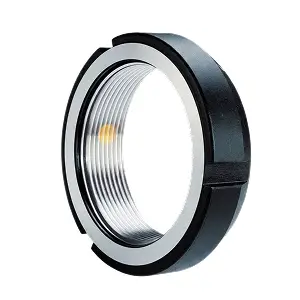
MF
Grinding
Hook wrench · nut exposed
M12×1 to M260×4 · h 14–36 mm
MF is the original 30° flank locknut, ground to 0.002 mm. Use it where the nut sits clear of the housing and a hook wrench has room to work.
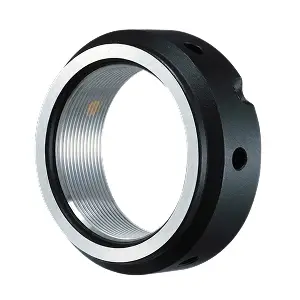
BF
Grinding
Hook wrench · nut recessed
M15×1 to M260×4 · h 14–40 mm
BF has a straight outer profile that stays reachable when the housing covers part of the nut, so a hook wrench still has a square surface to seat against. Same locking as MF.
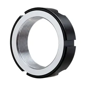
TMF
Grinding
Pin wrench
M20×1 to M200×3 · h 18–32 mm
TMF is driven through holes in its face with a pin wrench (pin spanner in UK and EU practice). It is ground only, with no precision-turned equivalent.
Precision turning
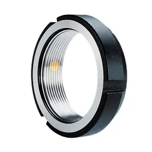
MFZ
Turning
Hook wrench · nut exposed
M12×1 to M260×4 · h 14–36 mm
MFZ is the precision-turned version of MF, with the same envelope and hook-wrench profile at 0.005 mm run-out instead of 0.002 mm.
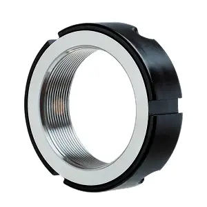
BFZ
Turning
Hook wrench · nut recessed
M15×1 to M260×4 · h 14–40 mm
BFZ is the precision-turned version of BF, with the same straight profile and hook-wrench access at 0.005 mm run-out.
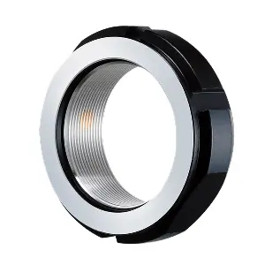
SFZ
Turning
Open-end wrench · two flats, to M75
M10×0.75 to M200×3 · h 14–32 mm
SFZ has two parallel flats for an ordinary open-end wrench, up to M75 only. It is the only type down to M10 × 0.75, and the type used most in Japan.
Why MF and BF Both Exist
MF came first. On a lot of machine designs the nut ends up half buried in its housing, and MF's sloped outer face leaves a hook wrench nothing square to bite on. BF was drawn to fix that. Same locking, same 30° flank, same materials, but a straight outer profile that stays reachable when the housing covers part of the nut. The two are functionally identical, so the choice comes down to how much of the nut your housing leaves exposed.
If you source across regions, this is worth knowing: the MF and BF split is largely a Taiwanese convention, and builders in Japan and Europe tend not to distinguish between the two. SFZ, with its wrench flats, is the type used most in Japan.
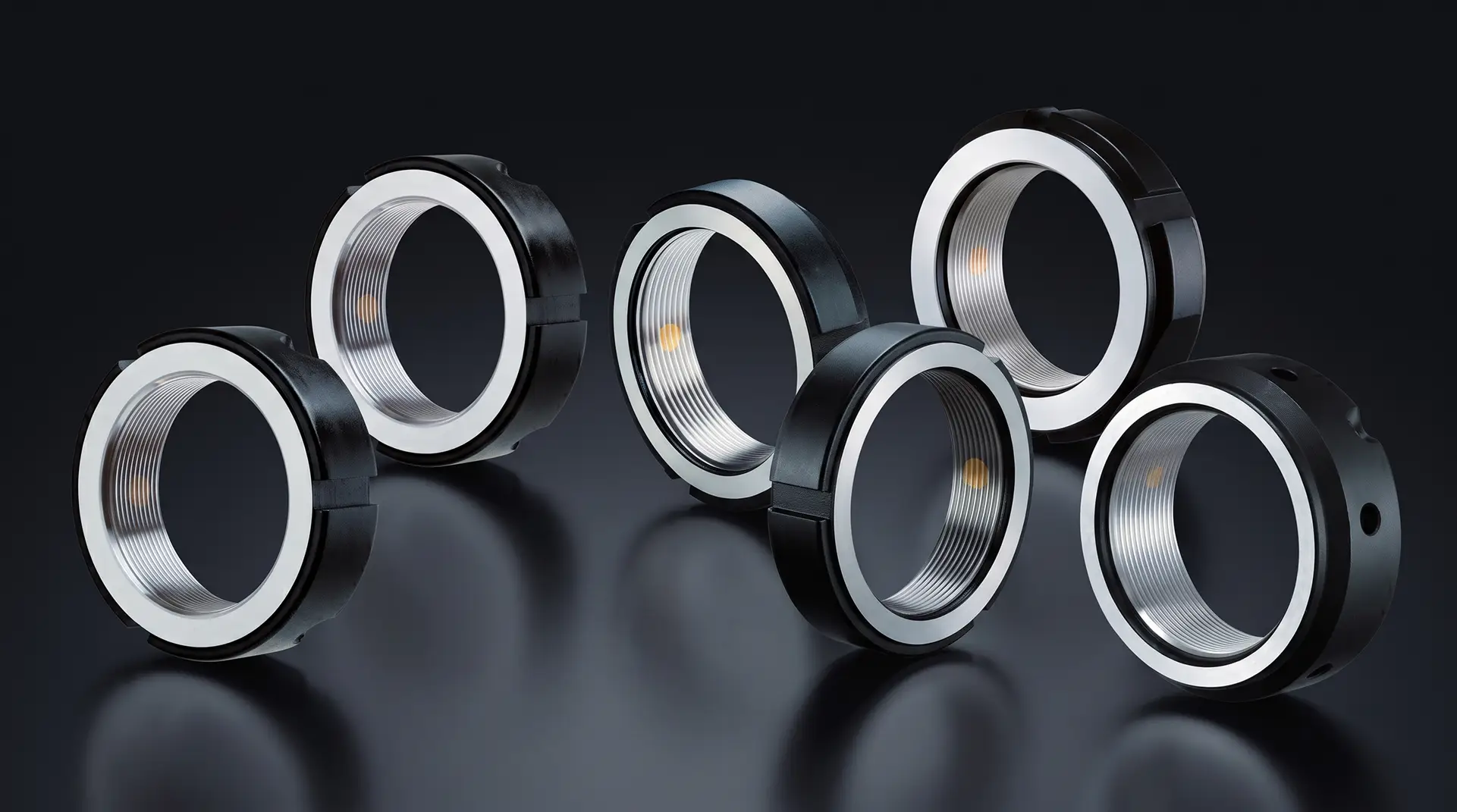
30° Flank Locknut Applications
These are the locknuts for the rest of the machine, the shafts and bearings that need to hold position reliably without spindle-grade run-out. Anywhere a threaded shaft carries a preloaded bearing, gear, or pulley is a candidate.
Gearboxes and reducers
Bearing and gear retention on input and output shafts, where reversing torque and thermal cycling gradually work on any locking method that relies on friction alone.
Pumps, fans, and blowers
Impeller and rotor retention. Continuous rotation with some out-of-balance load is exactly the condition that backs a plain nut off.
Bearing retention on secondary axes
Support bearings on machine axes where positioning accuracy matters but the axis isn't the spindle, so grinding-grade run-out would be paid for and not used.
Conveyor and roller assemblies
Long service intervals, dirty environments, and a strong preference for a nut that can be taken off and reused at rebuild.
Motor and drive shafts
Retention of couplings, pulleys, and drive components on the motor side of a transmission.
Shafts that can't take a keyway
Cutting a slot removes section where the shaft is often already at its limit. Flank locking needs no slot, so the shaft keeps its strength.
Cost-driven builds
Machinery where a turned-grade nut at 0.005 mm meets the drawing, and the budget won't carry a ground one.
Shared Specifications
- Material
JIS SCM440 / DIN 42CrMo4 / AISI 4140, alloy steel for quenching and tempering per ISO 683-2
- Hardness
HRC 28-32
- Thread Precision
ISO 4H per ISO 965-1
- Maximum Axial Run-Out
0.002 mm on MF, BF, TMF; 0.005 mm on SFZ, MFZ, BFZ
- Locking Method
Set screws driving a brass pad onto the thread flank at a 30° radial angle
- Set Screws
3 or 6 per nut (4 or 6 on SFZ, always 3 on TMF), sized M5 to M14, 4.8 to 100 Nm maximum per screw. MF, MFZ, TMF, and SFZ top out at M10 and 36 Nm; BF and BFZ go to M12 and 60 Nm from BF180X3.0P, and M14 and 100 Nm on BF260 and BFZ260
- Tightening
Hook wrench on MF, BF, MFZ, BFZ. Open-end spanner on SFZ up to SFZ75x2.0P, which is the largest size carrying wrench flats. Pin wrench on TMF
- Surface Finishing
Thread and contact surface ground (MF, BF, TMF) or precision turned (SFZ, MFZ, BFZ)
- Locking Accessories
None required
- Reusability
Reusable if handled properly
Tell Us What You Need. We'll Find the Locknut.

Give us the locknut code you use now and we'll find the NIKKI equivalent.

Describe the job, thread size, space, load, and we'll point you to the right NIKKI series.
Questions About the 30° Flank Locking Series
The 30° Flank Locking Series covers six locknut types in metric threads from M10 x 0.75 to M260 x 4, each locking through a brass pad driven onto the shaft thread flank at a 30° angle with no thrust washer or keyway. The questions below are the ones buyers ask before a first order.
Contact UsEach set screw drives a brass pad that presses against the thread flank of the shaft at a 30° radial angle. The pad grips the flank rather than the thread crest, which gives enough holding force to resist vibration without deforming the shaft. No slot, washer, or tab is needed.
They lock identically, with the same 30° flank, the same materials, and the same 0.002 mm run-out. What differs is the outer profile and therefore the wrench access. MF has a sloped outer face, so when the housing covers part of the nut a hook wrench has trouble seating. BF's straight profile stays usable in that situation. Choose by how much of the nut your housing leaves exposed.
Grinding grade (MF, BF, TMF) has both the thread and the contact face ground, holding maximum axial run-out to 0.002 mm. Precision-turning grade (SFZ, MFZ, BFZ) is finished by precision turning at 0.005 mm, and costs less. Material, hardness, and ISO 4H thread class are the same on both. The grade is in the model code: a Z means precision turned, so MFZ is the turned version of MF.
Choose the Ultra-Uniform Locking Series when preload stability sets the limit on the machine, typically machine tool spindles, ball screws, and high-speed rotating assemblies. Those locknuts lock at an optimized flank angle rather than 30°, keeping locking torque and surface pressure within 10% of each other. For general machinery, the 30° flank series does the job at lower cost.
The six types together cover metric threads from M10 x 0.75 up to M260 x 4, with outside diameters from 28 to 320 mm. Left-hand threads are ordered by adding L to the code. Inch threads replace the metric pitch with the TPI, for example MF30-U18. Full dimension tables are on each type's page.