

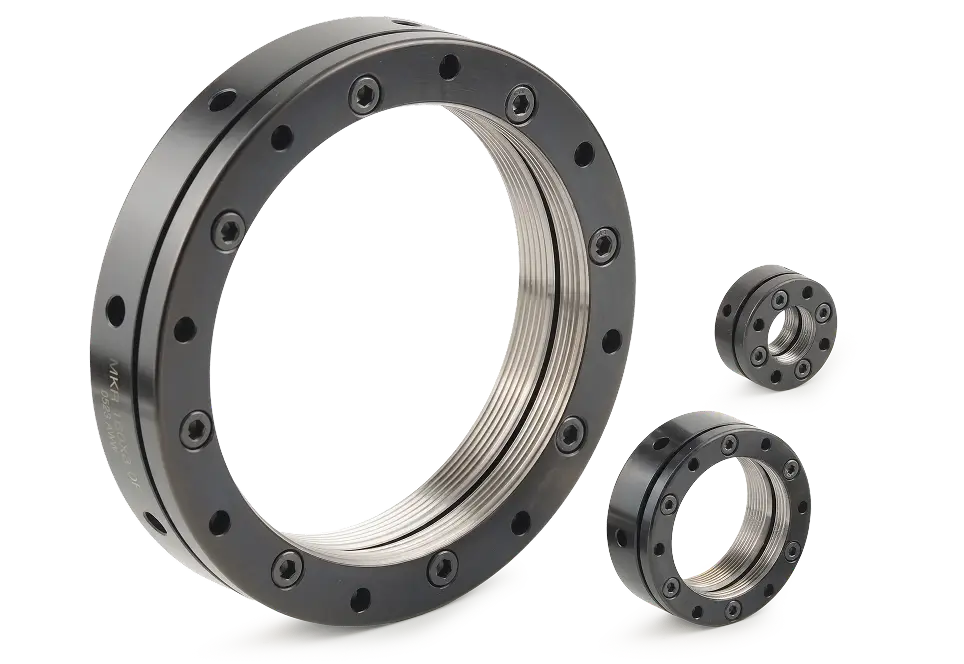

How Axial Locking Works
The locking screws in an axial locknut enter through the front face and run parallel to the shaft, so the tool that drives them approaches the nut head-on. Nothing has to reach the outside diameter, and that is the whole point of the arrangement. Once a bearing bore, a housing shoulder or a neighboring component covers the flank of the nut, a screw entering radially can no longer be reached with a hex key, while an axial screw still can.
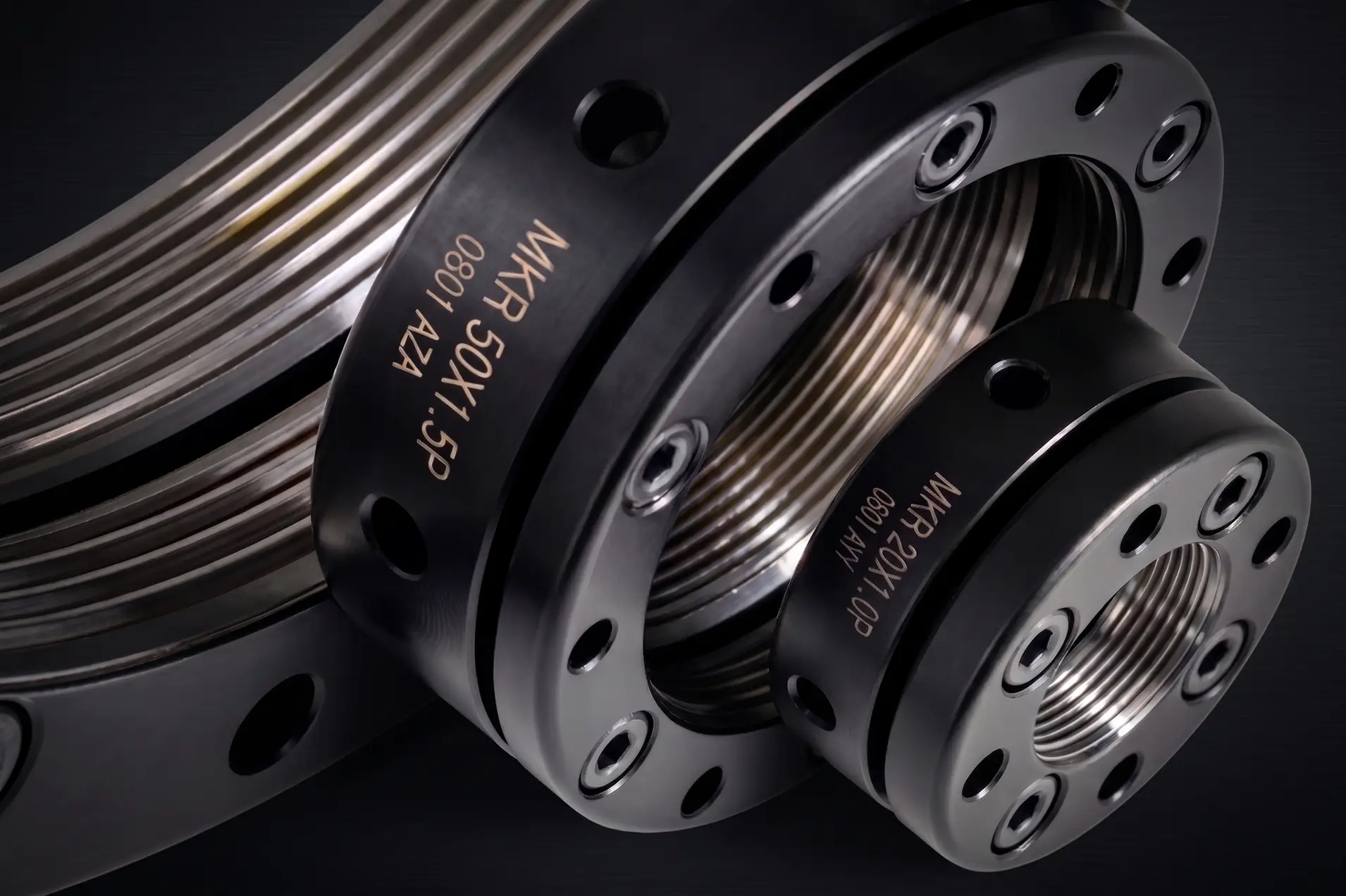
Two screw arrangements run through the series. MKR, MKK and MKW carry clamping screws, socket head cap screws of a specified length that are driven home once the nut is set to position. MA carries two set screws instead. The difference shows at disassembly: on the clamping-screw types the screws come off, the nut is loosened with an appropriate tool and lifted away, where a set-screw nut usually wants a light tap from a rubber mallet first.


Access · Locked from the front face
Spec: Screws parallel to the shaft axis · no radial access needed
The nut goes on locking in recessed bores and closed housings, where a hex key could never reach a screw entering through the outside diameter. On a good many designs this settles the series before any accuracy figure does.

Accuracy · Ground thread as well as ground face
Spec: 0.002 mm on MA · 0.005 mm on MKR, MKK and MKW
MA is the one type in the series with the thread area finished by high-precision grinding alongside the contact surface, which is what holds its maximum axial run-out to 0.002 mm. The other three grind the contact surface.

Range · Sizes the rest of the catalog skips
Spec: 58 sizes on MKR · from M10 x 0.75 at a 24 mm outside diameter
MKR lists intermediate threads such as M14, M16, M18, M22, M24, M26, M28, M32, M38, M42, M48, M52, M62 and M72 that no other NIKKI series carries. Its table also gives the helical angle of the thread for every size.

Service · Removal in three steps
Spec: Clamping screws on MKR, MKK and MKW
Loosen the clamping screws, loosen the nut with an appropriate tool, take it down. Assemblies that get opened for maintenance rather than scrapped tend to reward that, and all four types are reusable if handled properly.
Choosing Between MKR, MA, MKK and MKW
All four lock the same way, with screws driven through the front face parallel to the shaft, so the nut can be secured with its outside diameter buried. What differs is the finishing grade, whether the nut takes clamping screws or set screws, how many of them carry the load, and how much body height the type asks of the design.
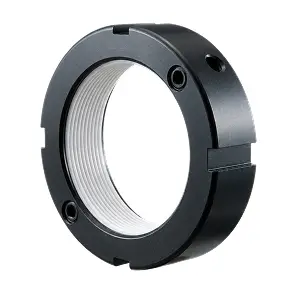
MA
0.002 mm
Two set screws · four wrench slots
M17×1 to M200×3 · h 15–37 mm
MA is the accuracy type in the series, ground on the thread area as well as the contact surface. It also carries the heaviest screws in the axial range, M12 at 56 Nm from MA135, spread over two positions rather than four or six.
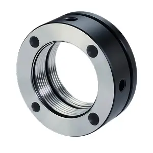
MKR
0.005 mm
Clamping screws · three to eight per nut
M10×0.75 to M200×3 · h 14–40 mm
MKR is the general-purpose axial locknut and by a wide margin the densest range NIKKI makes, at 58 sizes. It reaches M10 x 0.75, the smallest thread in the series, and it is the type to look at whenever the thread falls between the usual steps. MKR10 to MKR15 use a different body form from MKR16 upward.
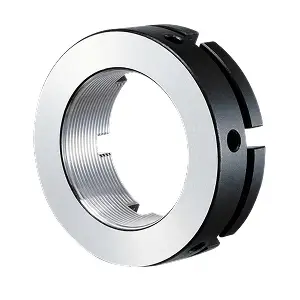
MKK
0.005 mm
Clamping screws · four to eight per nut
M15×1 to M130×2 · h 18–32 mm
MKK carries the heaviest clamping screws in the series, M10 at 36 Nm from MKK75, in a body no taller than 32 mm. Three threads, M30, M35 and M40, are listed in a second outside diameter, larger on M30 and M40 for a bigger contact face, smaller on M35 to fit a tighter housing bore.
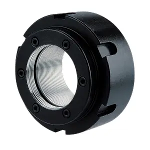
MKW
0.005 mm
Clamping screws · four or six per nut
M20×1.5 to M70×1.5 · h 28–46 mm
MKW is the tall type, 28 to 46 mm of body where the rest of the series runs 14 to 40 mm, which suits designs that would otherwise carry a separate spacer. The height sits in the code: MKW40-28 stands 28 mm high, MKW40-44 stands 44. Most threads to M50 are offered in two heights, and MKW runs a little softer than the others at HRC 25-28.
Axial Locknut Applications
These are the locknuts for assemblies that close up around the nut. Anywhere a bearing or a screw has to be retained and the flank of the nut disappears into a bore, a shoulder or an adjacent component is a candidate.
Recessed and counterbored housings
Bearing retention where the nut sits down inside the bore and only its front face stays exposed, so a hex key still reaches the screws straight down the axis.
Machine tool spindles
Bearing retention at the front and rear ends, where the cartridge or the housing frequently covers the outside diameter of the nut. MA is the type to specify here, at 0.002 mm.
Ball screws
Pre-tension at the fixed end and retention at the motor end, both of them usually built into confined supports.
Small threads below M15
MKR reaches M10 x 0.75 at a 24 mm outside diameter, and covers M12, M14 and M16 as well.
Assemblies opened for maintenance
Rebuilt gearboxes, spindle cartridges and pump ends, where the clamping-screw types come apart without tapping the nut.
Shafts that can't take a keyway
Cutting a slot removes section where the shaft is often already at its limit. Axial locking needs no slot, so the shaft keeps its strength.
Designs carrying a spacer
MKW bodies stand 28 to 46 mm high, so on some arrangements the nut takes up the length a separate ring would otherwise occupy.
Shared Specifications
- Material
JIS SCM440 / DIN 42CrMo4 / AISI 4140, alloy steel for quenching and tempering per ISO 683-2
- Hardness
HRC 28-32 on MKR, MA and MKK. HRC 25-28 on MKW
- Thread Precision
ISO 4H per ISO 965-1
- Maximum Axial Run-Out
0.002 mm on MA; 0.005 mm on MKR, MKK, MKW
- Locking Method
Screws driven through the front face, parallel to the shaft axis. Clamping screws on MKR, MKK and MKW; set screws on MA
- Locking Screws
Two to eight per nut depending on type and size. Clamping screws M3 to M10, 3 to 36 Nm maximum per screw. MA takes two set screws, M4 to M12, 2.2 to 56 Nm
- Body Height
14 to 46 mm across the four types, against 14 to 40 mm on the 30° flank series
- Outside Diameter
24 to 250 mm
- Tightening
The nut is set to position with an appropriate tool, then the screws are driven to the catalog torque with a hex key and a torque wrench. MA carries four wrench slots at every size; MKW carries four or six, dimensioned g x t in the tables
- Surface Finishing
Thread and contact surface ground (MA) or contact surface ground (MKR, MKK, MKW)
- Locking Accessories
None required
- Reusability
Reusable if handled properly
Tell Us What You Need. We'll Find the Locknut.

Give us the locknut code you use now and we'll find the NIKKI equivalent.

Describe the job, thread size, space, load, and we'll point you to the right NIKKI series.
Questions About the Axial Locking Series
The Axial Locking Series covers four locknut types in metric threads from M10 x 0.75 to M200 x 3, each locking through screws driven through the front face so the nut still holds when its outside diameter is buried. The questions below are the ones buyers ask before a first order.
Contact UsThe locking screws enter through the front face of the nut and run parallel to the shaft, so the hex key approaches head-on and never needs to reach the flank. That allows the nut to be locked and released in a recessed bore or a closed housing. No thrust washer or keyway is required, and the nut can be taken off and refitted.
MA is ground on the thread area as well as the contact surface and holds 0.002 mm axial run-out, locking with two set screws that take up to 56 Nm. MKR grinds the contact surface, holds 0.005 mm, and locks with three to eight clamping screws taking up to 25.5 Nm. MKR carries 58 sizes against MA's 33, including every thread below M17.
The MKR dimension table gives a helical angle for every size, from 2.48° at M12 x 1.5 down to 0.28° at M200 x 3. It corresponds to the lead angle of the thread, so the axial travel of the nut can be worked out from how far it has been turned. On a preloaded bearing arrangement that relationship is what you are setting, and having it on the datasheet saves calculating it from the pitch and the effective diameter each time.
Choose the Radial Locking Series where the outside diameter is still reachable after assembly and axial length is what the design has run out of. Those nuts stand around half the height of a 30° flank body and lock through set screws meeting the shaft at 90°. For general machinery with room around the nut, the 30° Flank Locking Series is the cheaper route, and where preload stability sets the limit on the machine, look at the Ultra-Uniform Locking Series.
The four types together cover metric threads from M10 x 0.75 up to M200 x 3, with outside diameters from 24 to 250 mm and body heights from 14 to 46 mm. Left-hand threads are ordered by adding L to the code and inch threads by adding U, for example MKR30x1.5P-L or MKR30-U18. Full dimension tables are on each type's page.